MIL-STD-1553 is widely used in military aircraft, aerospace systems and defense applications because it provides a controlled, predictable method of communication between electronic subsystems. However, even a properly designed 1553 network can experience communication problems during integration, testing, maintenance or system upgrades.
A Remote Terminal (RT) may stop responding to commands, communication may become intermittent, or a Bus Controller (BC) may report errors even though the connected equipment appears to be functioning normally.
Troubleshooting these problems requires more than checking whether messages are being transmitted. Engineers need to determine whether the fault originates in the physical bus, terminal configuration, message timing or communication sequence.
This guide explains the most common MIL-STD-1553 communication problems, their possible causes and a practical approach to identifying faults. It also examines how bus monitoring and analysis tools can help engineers isolate problems and verify corrective actions.
Common MIL-STD-1553 Communication Problems
The first step in troubleshooting a 1553 network is identifying the symptoms accurately. Different problems can produce similar error indications, so understanding what is happening on the bus is essential before changing hardware or software settings.
The following table summarizes common symptoms and possible areas to investigate:
| Symptom |
Possible Causes |
Initial Checks |
| No response from a Remote Terminal |
Incorrect RT address, power issue, connection fault or invalid command |
Verify RT configuration, power, command structure and physical connections |
| Intermittent RT responses |
Signal integrity problems, marginal connections, electrical interference or timing issues |
Compare successful and failed transactions and inspect physical-layer conditions |
| Unexpected or invalid status words |
Terminal configuration, incorrect status interpretation or reported terminal conditions |
Decode status bits and verify the expected RT address and message type |
| Response timeout |
Late or missing RT response, improperly decoded signal or BC timeout configuration |
Measure response timing and compare BC and RT observations |
| Parity or Manchester encoding errors |
Signal distortion, noise or transmitter/receiver problems |
Examine waveform quality and error distribution |
| Errors affecting multiple terminals |
Shared bus problem, termination issue or BC configuration error |
Compare affected RTs and investigate common bus components |
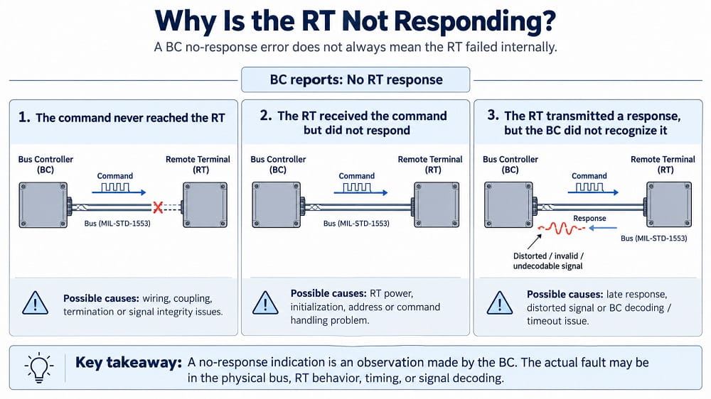
These symptoms provide a starting point, but they do not establish the root cause. For example, a missing RT response may indicate that the terminal never received the command, that it received the command but did not transmit a response, or that it transmitted a response the BC could not decode.
Distinguishing between these situations is central to effective troubleshooting.
Why Is a MIL-STD-1553 Remote Terminal Not Responding?
A missing RT response is one of the most common problems encountered during 1553 integration and testing.
In normal BC-to-RT communication, the Bus Controller sends a command and the addressed Remote Terminal responds according to the required message sequence. If the BC does not detect a valid response within the configured timeout period, it may report a no-response error.
However, the timeout indication does not necessarily mean the RT failed internally.
Incorrect Remote Terminal Address
Each RT on a MIL-STD-1553 bus must have a unique operational address. If the BC sends a command to the wrong address, the intended RT will not respond.
Duplicate RT addresses can also cause problems. When more than one terminal responds to the same command, overlapping transmissions may produce corrupted or undecodable responses.
Engineers should verify the configured RT address, confirm that it matches the command word and check that no other active terminal uses the same address.
Remote Terminal Power or Initialization Problems
An RT may be physically connected but unable to communicate because it has not completed initialization or is not operating in the expected mode.
Verify that the terminal is powered, initialized and configured to accept the intended command. If the device provides internal diagnostic information, compare its local status with the observed bus activity.
Physical Bus or Signal Integrity Issues
A command can be transmitted correctly by the BC but arrive at the RT with insufficient signal quality for reliable decoding.
Possible causes include incorrect termination, unsuitable coupling, wiring defects or excessive signal distortion.
Similarly, an RT may transmit a valid response locally while the returning signal is not successfully decoded by the BC.
This distinction becomes especially important when troubleshooting intermittent faults.
Incorrect Command or Message Configuration
An RT may not respond as expected if a command is invalid for its configuration, the subaddress is unsupported or the BC and RT disagree about the intended transfer.
Engineers should verify the complete command word, including RT address, transmit/receive direction, subaddress or mode-code field, and word count or mode-code value.
The expected response should also be checked against the message type. For example, broadcast commands are not followed by individual RT status responses.
MIL-STD-1553 Timing Errors and Response Timeouts
MIL-STD-1553 communication depends on defined timing relationships between messages and responses. A communication sequence may appear correct at the application level but still fail if an RT responds outside the permitted timing window or the BC does not recognize its response.
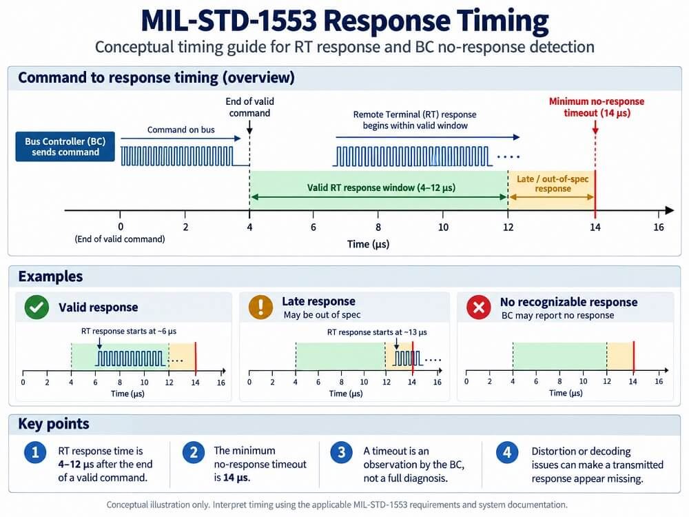
For a valid command requiring a response, the standard specifies an RT response time of 4 to 12 microseconds, measured at the defined interface reference point. The standard also specifies a minimum no-response timeout of 14 microseconds.
These limits provide an important reference when diagnosing late responses or apparent missing messages.
What to Check When a Timeout Occurs
Start by confirming that the BC transmitted a valid command and that the intended RT received it.
Next, determine whether the RT actually placed a response on the bus.
If a response is present, examine its timing, synchronization, encoding and signal quality. A bus monitor may reveal a status word that the BC failed to recognize.
If no response is present, investigate the RT configuration, initialization state and command handling.
Engineers should also review application-level timeout settings and retry behavior. These settings must be interpreted in relation to the requirements of the standard and the actual hardware implementation.
Why Intermittent Timing Errors Are Difficult to Diagnose
Timing problems are especially challenging when they occur only under certain operating conditions.
For example, a network may communicate correctly during a basic functional test but begin reporting errors when the BC schedule becomes more demanding or additional terminals become active.
In such cases, engineers should record the communication sequence under both successful and failing conditions.
Comparing command timing, response intervals and message ordering can help determine whether the problem is related to bus traffic, terminal behavior or the application controlling the communication.
Understanding MIL-STD-1553 Status Word Errors
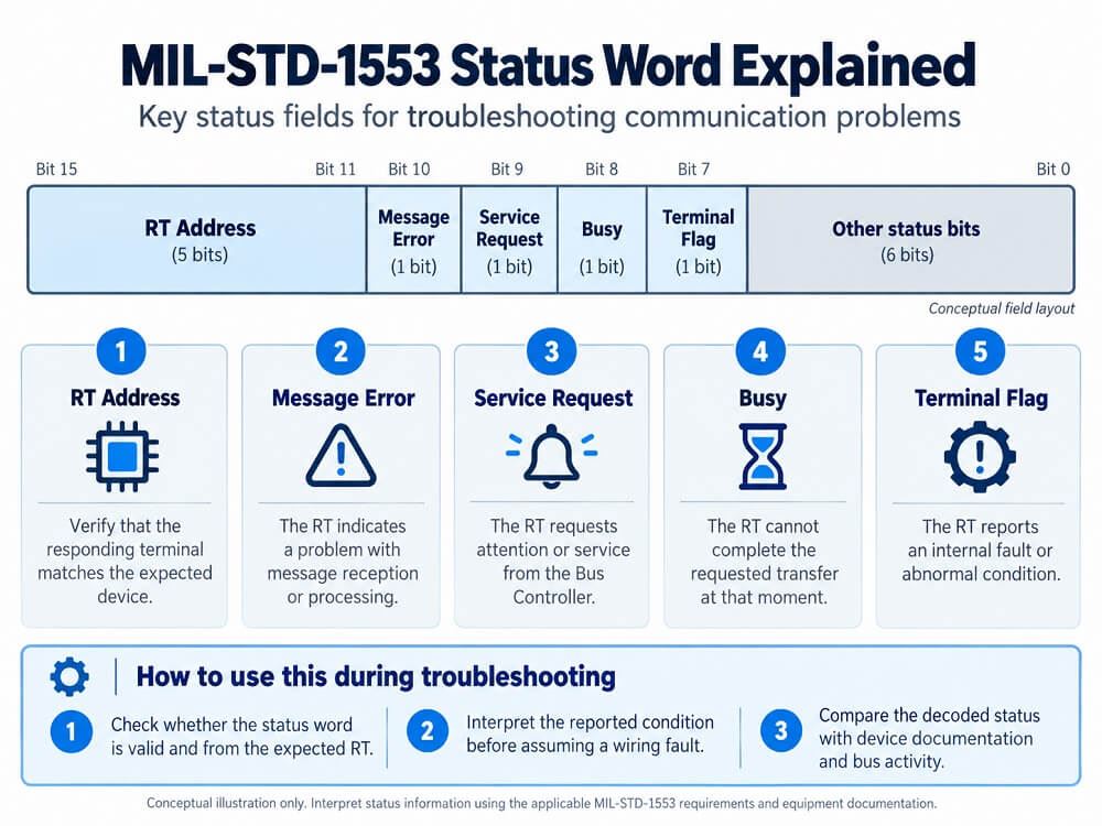
A MIL-STD-1553 status word provides information about the responding Remote Terminal and its operating condition.
An unexpected status word does not always mean that the communication itself has failed. In some cases, the RT is communicating correctly while reporting a condition that requires attention.
Engineers should distinguish between a status word that is physically invalid, one that contains unexpected values, and one that is valid but reports a terminal condition.
Important Status Word Fields to Examine
RT Address: Verify that the responding terminal address matches the expected device.
- Message Error Bit: Determine whether the RT is reporting a problem associated with message reception or processing.
- Service Request Bit: Check whether the RT is requesting service from the Bus Controller.
- Busy Bit: Determine whether the terminal is reporting that it cannot complete the requested transfer.
- Terminal Flag: Check whether the terminal is reporting an internal fault condition.
Not every unexpected status indication represents a physical-layer problem. The correct interpretation depends on the terminal implementation and applicable message sequence.
When investigating status errors, engineers should compare the decoded status word with the device documentation and the expected application behavior before making hardware changes.
Physical Bus Problems: Termination, Cabling and Coupling
Although MIL-STD-1553 communication is digitally controlled, its reliability depends heavily on the electrical characteristics of the physical network.
Problems with cables, termination or coupling can produce errors that resemble software or configuration faults.
Incorrect Bus Termination
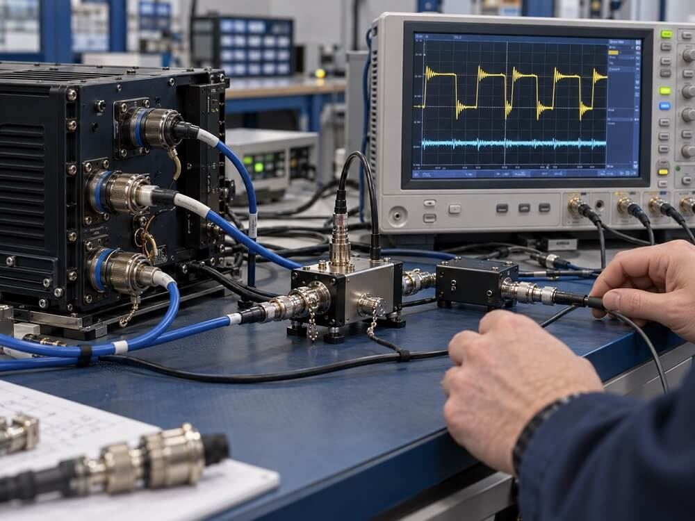
A MIL-STD-1553 bus requires appropriate termination at both ends of the main bus.
Incorrect or missing termination can cause signal reflections that interfere with reliable message decoding.
When investigating suspected termination problems, verify that the terminating resistors are installed at the correct locations and have values appropriate to the cable's characteristic impedance.
A commonly used 1553 cable has a nominal characteristic impedance of approximately 78 ohms, but the applicable bus design and component specifications should govern the actual installation.
Stub Length and Coupling Configuration
MIL-STD-1553 supports both transformer coupling and direct coupling, with different electrical characteristics and stub-length requirements.
Transformer-coupled connections provide isolation and generally support longer stubs than direct-coupled connections.
Direct-coupled stubs are typically limited to approximately one foot under the standard's recommended configuration, while transformer-coupled stubs may extend to approximately 20 feet, subject to the applicable design requirements.
Incorrect stub length, coupling selection or termination can affect signal amplitude, reflections and overall bus performance.
An important troubleshooting check is confirming that the interface hardware is configured for the actual coupling method used in the installation.
Excalibur's technical documentation specifically identifies termination, coupling configuration and stub length among the checks to perform when a BC reports that an RT did not respond, even though the RT reports receiving the command.
Cable and Connection Integrity
Physical defects can produce intermittent failures that are difficult to reproduce.
Engineers should investigate damaged cables, loose connections, shielding problems and changes introduced during maintenance or integration.
The objective is not simply to confirm electrical continuity, but to establish that the installed bus can preserve adequate signal quality under actual operating conditions.
Physical inspections and electrical measurements should be performed using approved procedures, with the appropriate equipment and without disturbing an operating aircraft system.
What to Check First: A Practical MIL-STD-1553 Troubleshooting Sequence
A structured troubleshooting sequence helps prevent unnecessary component replacement and reduces the risk of introducing additional faults.
The most efficient approach is to begin with the observable failure, isolate the affected portion of the network and then move from configuration checks to physical-layer analysis.
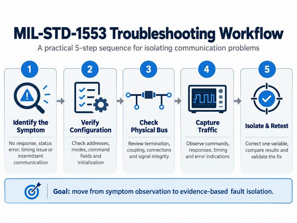
Suggested diagnostic sequence:
1. Identify the symptom
No response, status error, timing issue or intermittent communication
2. Verify BC and RT configuration
Addresses, operating modes, command fields and initialization
3. Check physical bus conditions
Termination, coupling, connections and signal integrity
4. Capture bus traffic
Commands, responses, timing and error indications
5. Isolate and verify the fault
Compare working and failing conditions, correct the cause and retest
Step 1: Identify the Scope of the Problem
Determine whether the fault affects one RT, several terminals or the entire bus.
A problem isolated to one RT may indicate a device-specific or stub-related issue. Similar failures across multiple terminals may indicate a shared physical bus problem or BC configuration issue.
Also determine whether the problem occurs consistently or only under particular operating conditions.
Step 2: Verify Configuration Before Changing Hardware
Check the BC schedule, terminal addresses, message definitions and expected responses.
Confirm that the equipment is operating in the intended BC, RT or Bus Monitor mode.
Review any recent firmware, software or configuration changes that might explain the observed behavior.
Step 3: Inspect the Physical Network
Verify the bus termination, coupling method, stub connections and cable installation.
Where appropriate, compare electrical measurements with the applicable system documentation.
If the platform uses redundant buses, compare traffic and fault behavior on Bus A and Bus B. Differences may help identify a problem in one physical path, although switching between buses should follow approved system procedures.
Step 4: Capture and Analyze Communication
Use a bus monitor or analyzer to examine the actual command and response sequence.
Look for missing or late responses, invalid words, error patterns and differences between expected and observed communication.
Recording the traffic is particularly useful when the fault is intermittent.
Step 5: Correct One Variable and Retest
Once a likely cause has been identified, make a controlled correction and repeat the test under comparable conditions.
Avoid changing multiple configuration parameters simultaneously, since doing so makes it difficult to determine which change resolved the problem.
Successful troubleshooting should conclude with evidence that the original fault has been eliminated and that normal communication remains stable.
How a MIL-STD-1553 Bus Monitor Helps Isolate Communication Problems
A MIL-STD-1553 bus monitor provides visibility into the traffic exchanged between the Bus Controller and Remote Terminals.
Unlike relying solely on application-level error messages, monitoring allows engineers to inspect the actual bus activity and identify where communication differs from expectations.
Capturing Commands and Responses
A bus monitor can record command words, data words and status words, allowing engineers to reconstruct the sequence of communication.
- This helps answer essential diagnostic questions:
Did the BC transmit the expected command?
- Was a response observed from the addressed RT?
- Did the response arrive within the expected timing window?
- Were unexpected messages or error indications present?
- Did the failure affect a single transaction or a recurring pattern?
For intermittent faults, continuous recording can preserve information that would otherwise disappear before an engineer can investigate it.
Analyzing Timing and Error Patterns
Monitoring tools can help identify timing irregularities, response failures and recurring message errors.
By comparing successful and failed transactions, engineers may identify relationships between communication errors and specific terminals, commands or operating conditions.
It is important to distinguish protocol-level monitoring from physical signal measurement. A decoded bus capture can show whether a word was recognized as valid, but diagnosing the underlying waveform distortion may require suitable oscilloscope or physical-layer test equipment.
Comparing Bus A and Bus B
Many MIL-STD-1553 installations use dual-redundant bus architectures.
When equivalent traffic can be observed on both buses, comparing the two paths may help determine whether a fault is associated with one transmission medium or with a terminal or configuration issue common to both.
Using Recorded Data for Further Analysis
Bus data recording is particularly useful during long-duration testing or when a communication problem cannot be reproduced on demand.
Captured traffic can be reviewed later, filtered by terminal address or message type, and compared with expected communication behavior.
For example, Excalibur Systems' EXALT Plus analysis software supports real-time and recorded avionics bus analysis, including raw data and engineering-unit displays. Its portable 1553 monitoring solution can capture all or selected traffic for subsequent analysis.
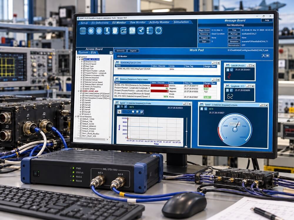
The primary benefit of such tools is improved fault visibility. They help engineers move from assumptions about what the network is doing to evidence of what actually occurred.
Troubleshooting Intermittent MIL-STD-1553 Bus Failures
Intermittent communication faults often require a different approach from permanent failures.
A bus that fails consistently can usually be investigated under controlled conditions. An intermittent fault may appear only during particular operating states, after extended use or when several subsystems communicate simultaneously.
The following practices can help isolate these problems.
Record the Conditions Surrounding Each Failure
Capture not only the error itself, but also the communication immediately before and after it.
Look for repeated patterns involving particular RT addresses, message types, bus selections or system operating modes.
Compare Normal and Fault Conditions
Establish a known-good communication baseline and compare it with recorded failure events.
Differences in response timing, missing messages or error frequency can provide clues about the underlying cause.
Investigate Whether the Fault Follows the Hardware or Configuration
Where permitted and practical, controlled substitution or testing with known-good equipment can help determine whether the problem follows a specific terminal, interface channel or configuration.
Such testing should be carried out using approved maintenance or laboratory procedures.
Avoid Assuming That Every Timeout Is an RT Failure
A timeout is an observation made by the controller, not a complete diagnosis.
The RT may have transmitted a response that was distorted, received too late or not recognized by the BC.
This is why independent traffic observation is valuable when the BC and RT appear to report conflicting results.
MIL-STD-1553 Troubleshooting Checklist for Engineers
Before replacing hardware or modifying a communication configuration, use the following checklist to confirm that the most common causes have been investigated.
Diagnostic checklist
- Bus Controller and Remote Terminal Configuration
- Verify that each active RT has a unique, correct address.
- Confirm BC, RT and monitor operating modes.
- Check command words, subaddresses, word counts and mode codes.
- Verify that terminals are powered and properly initialized.
Physical Bus and Signal Integrity
- Verify termination at both ends of the main bus.
- Confirm transformer or direct coupling matches the interface configuration.
- Inspect stub lengths, cabling, connections and shielding.
- Check whether errors affect Bus A, Bus B or both.
Timing and Message Validation
- Measure RT response times and review timeout behavior.
- Decode status words and check reported terminal conditions.
- Check for parity, synchronization or Manchester encoding errors.
- Compare expected message sequences with recorded traffic.
Monitoring and Fault Isolation
- Capture command, data and status words with a bus monitor.
- Compare successful and failed transactions.
- Record intermittent errors under representative operating conditions.
- Correct one identified cause at a time and repeat the validation test.
This checklist provides a starting point for systematic fault isolation. The exact diagnostic procedures and acceptance criteria should always be based on the applicable MIL-STD-1553 requirements, equipment documentation and system-specific test plan.
Conclusion: A Systematic Approach to MIL-STD-1553 Troubleshooting
MIL-STD-1553 communication problems can originate from several layers of a system, including terminal configuration, message timing, physical bus conditions and application-level behavior.
A missing response does not automatically indicate a failed Remote Terminal, just as an unexpected status word does not necessarily indicate a wiring problem. Effective troubleshooting depends on separating symptoms from their possible causes and collecting enough evidence to identify the actual failure mechanism.
By verifying configurations, checking physical-layer conditions, analyzing message timing and recording bus traffic, engineers can isolate communication problems more efficiently and avoid unnecessary hardware replacement.
Ultimately, a structured diagnostic process supported by reliable bus monitoring helps maintain the predictable communication performance that MIL-STD-1553 systems are designed to deliver.