We understand the case as follows:
• The RT receives the command from the BC, and records that it
responded with the correct RT status word.
• However, the BC does not see the RT response.
Please check that
• this is the only RT (with this RT number) connected on the bus
• you have connected 78 Ohm termination to the ends of the 1553 bus
• the modules on the 1553 bus are connected with the appropriate
coupling method, such that the dip switch settings on the 1553Px
module on the card match the actual coupling method, transformer
coupled, or direct coupled (as per the User's Manual, section 7.3)
• cable length, how long is the cable from the stub to the bus (the
specification suggests: for direct coupling less than one foot; for
transformer coupling up to 20 feet)
Our modules simulate 1553 communications.
Any specific module is one single channel of 1553 communications. That is, a
module can play only one of the three available modes at one time: BC, RT,
Monitor.
A Monitor can run opposite a BC and an RT, and record all the traffic, assuming
that all three are on the same 1553 bus.
In BC & RT modes, we have an additional section of memory that records all bus
traffic (like a quasi-Monitor, called Internal Concurrent Monitor), with each
message listed individually in series, and with room for over 400 messages.
Multi-function (Px) means that
- RT mode can simulate (activate) any number of RTs, up to all of the RTs, 0-31
- BC mode can simulate (activate) any number of RTs (say, to fill in for those RTs
for which you have no real RT or other channel playing RT mode)
- error injection exists (is available, can be set) in both BC & RT modes
Single function (PxS) means that
- RT mode can simulate (activate) only one RT (any one of them, from 0-31)
- BC mode cannot simulate (activate) any RTs
- no error injection is allowed in any mode (BC, RT)
The 1760 version of the module is a superset of the 1553 version. That is, all of the features of 1553
exist in the 1760 module, plus there are a few additional features that exist only in the 1760 version.
The API is the same, with some additional functions that implement the additional 1760 features.
These features are:
1. Header Word
Some SubAddresses (1,11,14) require that the first data word be a specific value (in specific cases).
These are listed in the manual (hardware & software), under sections called "Header Word" or
"1760 Options".
• This is designed as per the 1760 specification.
• We allow you to disable/suppress this requirement, using function Set_Header_Exists_Px, with
parameter HEADER_DISABLE.
2. Checksum
In BC mode, you can set a message to require a checksum as the last data word, as defined in the
manuals (using function Enable_Checksum_Px). The module will calculate the checksum and place
it as the last data word in the BC2RT message, or check if the received checksum in an RT2BC
message is correct.
[ You can also set that the checksum for a BC2RT message should have an error injected into it
(using function Enable_Checksum_Error_Px). ]
In RT mode, you can set that certain datablocks (for Rx or Tx) can be designated to require a
checksum in the last data word (using function Set_Checksum_Blocks_Px). A datablock can be
associated with any RTid (Rx or Tx), using function Assign_RT_Data_Px.
In Monitor mode, the module always looks for the checksum and sets a flag in the message status
word if the checksum word is not correct.
Here is sample code to call these functions:
-----------------
for BC mode:
// Enable_Checksum_Px();
msgentry = 0;
enable = ENABLE; // or DISABLE;
status = Enable_Checksum_Px(handle, frameid, msgentry, enable);
if (status < 0)
{
printf("Enable_Checksum_Px returned error: %s\n",Print_Error_Px(status));
printf("Press any key to exit the program ... ");
_getch();
}
else
printf("Enable_Checksum_Px returns status value %d\n", status);
// Enable_Checksum_Error_Px();
msgentry = 1;
enable = ENABLE; // or DISABLE;
status = Enable_Checksum_Error_Px(handle, frameid, msgentry, enable);
if (status < 0)
{
printf("Enable_Checksum_Error_Px returned error: %s\n",Print_Error_Px(status));
printf("Press any key to exit the program ... ");
_getch();
}
else
printf("Enable_Checksum_Error_Px returns status value %d\n", status);
-----------------
for RT mode:
// Set_Checksum_Blocks_Px();
int csum_blocks=50;
status = Set_Checksum_Blocks_Px(handle, csum_blocks);
if (status < 0)
{
printf("Set_Checksum_Blocks_Px returned error: %s\n",Print_Error_Px(status));
printf("Press any key to exit the program ... ");
_getch();
}
else
printf("Set_Checksum_Blocks_Px returns status value %d\n", status);
(a) Use function Set_RT_Active_Px to make the RT active/simulated. If your module is multifunction Px, then you can activate multiple RTs (numbered from 0-31). If your module is single-function PxS, then you can activate only one RT.
(b) Use functions Assign_RT_Data_Px to associate a data block with some RTid, and
Load_Datablk_Px to load data into the data block.
(c) Somehow decide when you want to change the data (interrupt, or after some given
time), and call Load_Datablk_Px with the new data. If you want a built-in mechanism that
will help ensure data integrity (so that you do not change the data block while it is being
transmitted, which may result in a mixed block of old & new data), then you can use double
buffering, using function Assign_DB_Datablk_Px.
If you want to use multiple (up to 16) data blocks for a single RTid, use function
Set_RTid_Multibuf_Px.
(d) Use function Get_Next_Message_RTM_Px or Get_Next_Mon_Messgae_Px to extract
messages from the Internal Concurrent Monitor.
The software manual entry for these functions shows the message block (structure) content;
and what values are returned (e.g., enomsg = -18, if there is no additional new unread
message at present). You can then parse the command word and decide to take different
actions depending on the message type.
(a) Use function Set_RT_Active_Px to make the RT active/simulated. If your module is multi-function Px, then you can activate multiple RTs (numbered from 0-31). If your module is single-function PxS, then you can activate only one RT.
(b) Use functions Assign_RT_Data_Px to associate a data block with some RTid, and
Load_Datablk_Px to load data into the data block.
(c) Somehow decide when you want to change the data (interrupt, or after some given
time), and call Load_Datablk_Px with the new data. If you want a built-in mechanism that
will help ensure data integrity (so that you do not change the data block while it is being
transmitted, which may result in a mixed block of old & new data), then you can use double
buffering, using function Assign_DB_Datablk_Px.
If you want to use multiple (up to 16) data blocks for a single RTid, use function
Set_RTid_Multibuf_Px.
(d) Use function Get_Next_Message_RTM_Px or Get_Next_Mon_Messgae_Px to extract
messages from the Internal Concurrent Monitor.
The software manual entry for these functions shows the message block (structure) content;
and what values are returned (e.g., enomsg = -18, if there is no additional new unread
message at present). You can then parse the command word and decide to take different
actions depending on the message type.
The simple answer is yes.
We have a feature called Internal Concurrent Monitor (ICM) in both BC and RT modes. This
sets aside a section of memory on the module to act as a quasi-Monitor (within the confines
of the BC or RT).
In the ICM memory area, we store a record of all message traffic on the bus. Effectively, we
have a Monitor stored within the memory area of the RT. All data words that the BC sends
over the bus to an RT (BC2RT message), and all data words transmitted by some RT over the
bus (RT2BC or RT2RT messages) are recorded in the ICM, along with the command words &
status words, and an attached timetag stamp (plus an additional internally built message
status word).
Each message is stored sequentially in the buffer. Buffer size is defaulted to 409 blocks.
You can read more about this memory area in the User's Manual (hardware), chapter 5.
You can read up on the API functions used for monitoring in the Programmer's Reference
(software). Use functions Get_Next_Message_RTM_Px or Get_Next_Mon_Message_Px.
Here is a snippet from the software manual:
Get_Next_Mon_Message_Px reads the message block following the message block read in
the previous call to Get_Next_Mon_Message_Px.
This function can be used in all modes, instead of:
Get_Next_Message_Px in Monitor mode,
Get_Next_Message_BCM_Px in BC mode or
Get_Next_Message_RTM_Px in RT mode.
Bottom line: If you want to be an RT and still be able to get all of the message contents as
individual messages (aka Monitor), you should be able to do this with a single module in RT
mode, reading messages from the ICM. This works for multi-function Px modules, as well
as for single-function PxS modules.
Please see our demo program demo_cmon.c which uses this methodology.
Unfortunately the answer is no.
Our software drivers need to match the architecture and registers of the respective
modules. Even though both module families are for the MIL-STD-1553
communications protocol, the chip architecture of the two families is different.
Therefore, the software APIs are inherently different. So much so, that it is fairly
impossible (in our opinion) to port code from one module type to the other. Porting
code would instead require a rewrite.
The 1553MCH family is based on a chip that we buy from another company. This
module family has basically been replaced by our own M4K1553PxS module family.
The 1553Px family is our own in-house development. We have moved to our third
generation of chips for this family, keeping the same basic architecture and registers,
so that customers can easily replace an older card with a newer one.
The simple answer is yes.
We have a feature called Internal Concurrent Monitor (ICM) in both BC and RT modes. This
sets aside a section of memory on the module to act as a quasi-Monitor (within the confines
of the BC or RT).
In the ICM memory area, we store a record of all message traffic on the bus. Effectively, we
have a Monitor stored within the memory area of the RT. All data words that the BC sends
over the bus to an RT (BC2RT message), and all data words transmitted by some RT over the
bus (RT2BC or RT2RT messages) are recorded in the ICM, along with the command words &
status words, and an attached timetag stamp (plus an additional internally built message
status word).
Each message is stored sequentially in the buffer. Buffer size is defaulted to 409 blocks.
You can read more about this memory area in the User's Manual (hardware), chapter 5.
You can read up on the API functions used for monitoring in the Programmer's Reference
(software). Use functions Get_Next_Message_RTM_Px or Get_Next_Mon_Message_Px.
Here is a snippet from the software manual:
Get_Next_Mon_Message_Px reads the message block following the message block read in
the previous call to Get_Next_Mon_Message_Px.
This function can be used in all modes, instead of:
Get_Next_Message_Px in Monitor mode,
Get_Next_Message_BCM_Px in BC mode or
Get_Next_Message_RTM_Px in RT mode.
Bottom line: If you want to be an RT and still be able to get all of the message contents as
individual messages (aka Monitor), you should be able to do this with a single module in RT
mode, reading messages from the ICM. This works for multi-function Px modules, as well
as for single-function PxS modules.
Please see our demo program demo_cmon.c which uses this methodology.
1. As per the 1553 spec, the BC is the active player in the protocol, creating a bus list of messages which it
transmits over the 1553 bus. The messages are of multiple types including BC2RT (BC sends the data words
to the RT), RT2BC (BC requests that the RT transmit back data), RT2RT (BC requests that one RT receive
data, and a different RT transmit the data).
Since the BC must verify that the message was properly completed, the protocol rules include that the BC
will verify (for RT2BC & RT2RT messages) that it detected the receipt of the requested number of words
from the RT.
So, by nature of the protocol, the BC will receive the data transmitted by the RT. And, our API supplies
functions for retrieving any message in the bus list, at any given time.
2. To help retrieve messages, we added a feature called Internal Concurrent Monitor (ICM) in both BC and
RT modes. This sets aside a section of memory on the module to act as a quasi-Monitor (within the confines
of the BC or RT).
In the ICM memory area, we store a record of all message traffic on the bus. Effectively, we have a Monitor
stored within the memory area of the BC. All data words that the BC sends over the bus to an RT (BC2RT
message), and all data words transmitted by some RT over the bus (RT2BC or RT2RT messages) are
recorded in the ICM, along with the command words & status words, and an attached timetag stamp (plus
an additional internally built message status word).
Each message is stored sequentially in the buffer. Buffer size is defaulted to 409 blocks.
You can read more about this memory area in the User's Manual (hardware), chapter 5.
You can read up on the API functions used for monitoring in the Programmer's reference (software). use
functions Get_Next_Message_BCM_Px or Get_Next_Mon_Message_Px.
Here is a snippet from the software manual:
Get_Next_Mon_Message_Px reads the message block following the message block read in the previous call
to Get_Next_Mon_Message_Px.
This function can be used in all modes, instead of:
Get_Next_Message_Px in Monitor mode,
Get_Next_Message_BCM_Px in BC mode or
Get_Next_Message_RTM_Px in RT mode.
3. Bottom line: If you want to be a BC and still be able to get all of the message contents as individual
messages (aka Monitor), you should be able to do this with a single module in BC mode, reading messages
from the ICM.
Please see our demo program demo_cmon.c which uses this methodology.
(a) Set up your bus list to transmit a BC2RT (Receive) message to the Receive SA,
followed by an RT2BC message to the Transmit SA. You can set this bus list to be
transmitted one shot, multiple times (up to 255), or continuously.
(b) On the RT side, data is stored in data blocks. You can assign a specific data block to a
specified RTid, which is a designation of RT number, SA number, and direction of data
transmission (Receive or Transmit, from the RT’s perspective); using function
Assign_RT_Data_Px.
If you do not assign a data block to your RTid, then the default data block assigned is
number 0. In this case, the last data received for a Receive (BC2RT) message will be the
data that is transmitted for a Transmit (RT2BC) message.
(c) Call the function Assign_RT_Data_Px twice, using the same data block number for
the two RTid’s, where the RTid’s have the same RT & SA, but the direction of one is 0
(Receive) and the direction of the other is Transmit (1).
(a) One of the features of the 1760 specification is the requirement that some
SubAddresses (1, 11, 14), for some types of messages, require that the first data word
(called a header word) be a specific pre-defined value.
If the first data word does not match the pre-defined value, then the error bit is turned
ON in the Message Status Word. This indicates that the “Header Word received does
not match the value set in the Header Value Table.”
(b) To bypass this error, so that it does not get generated, you can call function
Set_Header_Exists_Px for the specific desired SubAddress, with parameter enable set
to HEADER_DISABLE. In this case, the error bit will not be turned ON.
1. Major frame is the list of all the messages in the current frame. We place a bus list of messages in a
FRAME struct, as defined in file bcrun.h, and used in all the BC demo programs: demo_bc1, demo_bc2,
demo_2crd, demo_2md, demo_async, demo_cmon, demo_minor.
You can create multiple major frames (call Create_Frame_Px to create each individual frame), and then
decide which one is the (current) frame to transmit, using Start_Frame_Px.
You can create an asynchronous frame which can then be transmitted at will, in the middle of the
transmission of the major frame, when the current message completes being transmitted over the bus
(using functions Select_Async_Frame_Px and Send_Async_Frame_Px). When the async frame completes
transmission, control is returned to the next message of the major frame.
2. Within any list of messages, each message is created using function Create_1553_Message_Px. This
assigns an id to the message. Each message is added to its desired frame into the FRAME structure, with
two parameters: id and intermessage gaptime. The intermessage gaptime is the time the firmware is to
wait between the completion of one message and the beginning of transmission of the next message.
3. The major frame time (set by calling function Set_Frame_Time_Px) sets the total frame time for all of
the messages in our major frame. The firmware processes & transmits all the messages in the major
frame, all the while keeping an accounting of how much time was spent from the beginning of the first
message transmission (by setting a counter equal to the frame time, and counting down).
If all the messages have been transmitted and the counter is not yet 0, then the firmware waits until the
counter gets to 0 before continuing. That is, if the frame is scheduled to be transmitted more than once,
either continuous using Run_BC_Px(handle, num_times), where num_times=0, or N-times where
num_times is a number between 2-255, the firmware will wait until the counter counts down to 0 before
going back to retransmit the frame.
4. Minor frames are designed to be used to create groups of messages that need to be transmitted at
specific intervals, say every 10 or 20 msec.
For example, if you have
• group A of messages that need to be transmitted every 20 msec,
• group B of messages that need to be transmitted every 10 msec,
• group C of messages that need to be transmitted every 40 msec,
then you determine the lowest common denominator of the time periodicity (in this case 10 msec) and
group the messages using Minor Frames. In this case, your Minor Frame (MF) time will be 10 msec. You
will group the messages with a "marker" (MF) message in between groups.
The MF message (Create_1553_Message_Px with message type MINOR_FRAME) is used to tell the
firmware how long to count down before allowing the firmware to move to the next group of messages.
Hence, we use MF markers between every set of messages that form a group. One MF marker message at
the beginning of the major frame list, and then groups of messages delineated by MF messages. At the
end of the major frame we do not place a MF message.
Since we want the MF time to drive the timing, we set the major frame to (Set_Frame_Time_Px) to a very
small number, say 10 (this parameter is in microsec).
For the example I started above, your major frame would look like this:
MF-B-MF-B-A-MF-B-MF-B-A-C
5. You can read more about minor frames in the User’s Manual (hardware manual), section 3.5.
This requires a short tutorial on the concepts of 1553 :
We start with a bus, over which the 1553 traffic flows. There are three players: BC (Bus Controller), RT
(Remote Terminal), Mon (Bus Monitor).
The BC controls the whole flow of messages. The BC is active, and the other players (RT and Mon) are
passive. All messages are initiated by the BC, who sends out the command word. All players on the bus
listen for a command word, and determine if it is for them to "pick up."
The command word includes information as follows:
• target RT-SA (Remote Terminal number, SubAddress number)
• word count
• in which direction is the data traveling, from the perspective of the target RT: Receive (BC2RT)
means that the RT receives the data words (and the BC sends the data words); Transmit (RT2BC)
means that the RT transmits the data words
[ See Appendix B MIL-STD-1553 Message Formats in the manuals for a description of the different
message types in 1553. ]
RT status word (see Appendix A MIL-STD-1553 Word Formats in the manuals)
• is either the first word returned by the RT (followed by data), or is sent by the RT after receiving
all the data word (depending on the message type)
• contains the RT address, acting as an ACKnowledge to say "I am here"; has a number of other
information bits (not mandatory)
• has one bit which can indicate to the BC that the RT wants service (SRQ bit), for which the BC will
make a new message requesting this information from the RT
The firmware for the different players (in the given card or box) is built according to the rules of the 1553
protocol. Hence, any player on the bus who receives the command word knows exactly what to expect
next (command word, data word, status word), and will report an error if the unexpected occurs.
Our 1553 GUI application, MerlinPlus, in each of the modes, takes the command word, parses it, and
decides how to display the message based on the parsed result. It displays command word, command
type, target RT-SA, word count, error or not.
1. As per the 1553 spec, the BC is the active player in the protocol, creating a bus list of messages which it
transmits over the 1553 bus. The messages are of multiple types including BC2RT (BC sends the data words
to the RT), RT2BC (BC requests that the RT transmit back data), RT2RT (BC requests that one RT receive
data, and a different RT transmit the data).
Since the BC must verify that the message was properly completed, the protocol rules include that the BC
will verify (for RT2BC & RT2RT messages) that it detected the receipt of the requested number of words
from the RT.
So, by nature of the protocol, the BC will receive the data transmitted by the RT. And, our API supplies
functions for retrieving any message in the bus list, at any given time.
2. To help retrieve messages, we added a feature called Internal Concurrent Monitor (ICM) in both BC and
RT modes. This sets aside a section of memory on the module to act as a quasi-Monitor (within the confines
of the BC or RT).
In the ICM memory area, we store a record of all message traffic on the bus. Effectively, we have a Monitor
stored within the memory area of the BC. All data words that the BC sends over the bus to an RT (BC2RT
message), and all data words transmitted by some RT over the bus (RT2BC or RT2RT messages) are
recorded in the ICM, along with the command words & status words, and an attached timetag stamp (plus
an additional internally built message status word).
Each message is stored sequentially in the buffer. Buffer size is defaulted to 409 blocks.
You can read more about this memory area in the User's Manual (hardware), chapter 5.
You can read up on the API functions used for monitoring in the Programmer's reference (software). use
functions Get_Next_Message_BCM_Px or Get_Next_Mon_Message_Px.
Here is a snippet from the software manual:
Get_Next_Mon_Message_Px reads the message block following the message block read in the previous call
to Get_Next_Mon_Message_Px.
This function can be used in all modes, instead of:
Get_Next_Message_Px in Monitor mode,
Get_Next_Message_BCM_Px in BC mode or
Get_Next_Message_RTM_Px in RT mode.
3. Bottom line: If you want to be a BC and still be able to get all of the message contents as individual
messages (aka Monitor), you should be able to do this with a single module in BC mode, reading messages
from the ICM.
Please see our demo program demo_cmon.c which uses this methodology.
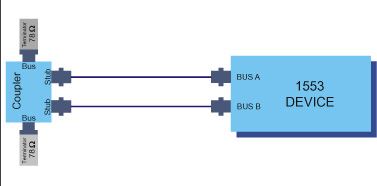
The 1553B card or module has two cables for each 1553B channel, one cable for Bus A
and one cable for Bus B. Normal 1553B communication requires connecting all bus A
cables to one 1553B bus, and all bus B cables to another 1553B bus.
A 1553B bus can be a stub coupler with some number of stubs, and with a terminating
resistor on the stubs at the ends of the bus.
Please see the FAQ document titled “1553 Bus Connections diagram.pdf” for a diagram
with a number of 1553B devices connected to busses A & B.
Our demo_loopback program performs two kinds of loopback:
• Internal loopback test: checks connections internal to the card; does not require
any external cable connections to perform the test
• External loopback test: checks connections external to the card; requires
connecting the bus A and bus B cables to the same 1553B bus
Here is a diagram of the cable connections needed for the External loopback test.
1. It is necessary to install the software tools for the specific module/board, in this case, M4K1553Px module
on EXC-4000PCI board. This installs two DLLs - one for the 4000PCI base board, and one for the M4K1553Px module.
The DLL name is different:
M4K1553Px module: Exc1553Px.dll (for Borland compiler) or Exc1553PxMs.dll (for Microsoft
compiler). px.dll or pxms.dll are also available.
PCI/Px board: pcipx.dll (for Borland compiler) and pcipxms.dll (for Microsoft compiler).
In your project file, replace the use of pcipx.lib/pcipxms.lib with Exc1553Px.lib/Exc1553PxMs.lib, or rename
these new DLLs (Exc1553Px[Ms]) with the previously used names (pcipx[ms]).
2. The function names have been preserved, almost in entirety, for backwards compatibility. This assumes
that you have only one module on the board. If you have more than one module, it will be necessary to
move to the some of the new function names. Please see item #4.
3. Initialize/Release differences:
PCI/Px board : Init_Card initializes all modules on the board. Release_Card releases resources for all modules.
M4K1553Px module: Init_Module_Px initializes only the specific module as per the function
parameters. Use Release_Module_Px to release resources for this specific module.
NOTE: If you are porting a project from PCI/P1 to EXC-4000PCI with one M4K1553Px module (in position 0),
then you can use the existing application source code as is, including function calls Init_Card and
Release_Card. We added these functions to the DLL (in source file initcard.c) to handle PCI/P1 or PCI/EP
cards.
NOTE: If you have an EXE that ran on a PCI/P1, and want to run the EXE on a EXC-4000PCI with one
M4K1553Px module (in position 0) without recompiling, then install the M4K1553Px software tools, rename
the DLL (for the appropriate compiler) to the same name that was used in the application (pcipx.dll or
pcipxms.dll), and run the EXE.
4. Init_Module_Px takes two arguments:
device_number - use default value of 25, or as defined using ExcConfig
module_number - the specific module on the board that you wish to initialize (0,1,2,3)
Upon success, the function return value is designated as the "handle" for this module. Use this "handle" as
the first (additional) parameter in all function calls.
All function names have been modified to have a suffix of "_Px". If you wish to use the old function names,
which do not use the "handle" parameter, please see item #5.
5. To use the old function names (without the "_Px" suffix, and without the additional "handle" parameter),
include the file proto_px_back.h in your application. This includes the function prototypes for the backwards
compatible functions. Then, replace Init_Card with Init_Module_Px; and Release_Card with Release_Module_Px.
6. If you have more than one module, you must call the function Init_Module_Px for each module. The
function returns a "handle" value.
All function calls apply to the currently selected module. If you use the new function names (with the suffix
_Px), then use the "handle" for this module as the first parameter. If you want to use the old function
names, include the file proto_px_back.h in your application, and proceed as in item #7.
7. Using old function names: Use Select_Module to select a specific module. Then call the mode specific
functions that you wish to apply to this module.
Therefore, to switch to another module (i.e., to apply function calls to another module), call
Select_Module(other_module_number), and then call the mode specific functions that you wish to apply to
this module.
To switch back to the first module, call Select_Module(first_module), and then call the mode specific
functions that you wish to apply to this module.
In BC mode, for each message (in the bus list) that is transmitted over the 1553 bus,
the module/card generates an internal status word. The hi bit of this status word
indicates that the message completed processing (value of 0x8000), and additional
bits indicate errors. These functions return (as an output parameter) this status word,
whose bits are defined in the manuals.
The return value of these functions is a signed integer. 0 means all is OK; a negative
number means that there is a problem.
The output parameter message status word is valid only if the hi bit (value of 0x8000)
is set (indicating message complete).
After calling this function, the message status value is zeroed out. So, if you call the
function twice in a row, before transmitting the message again, you will get a return
message status word value of 0.
We suggest using the newer (replacement) function Get_Msgentry_Status_Px instead
of the old (legacy) function Get_Msg_Status_Px. The bits returned are identical for
both functions.