The EXC-8000ccVPX is part of the 8000 family of multiprotocol carrier boards. This conduction cooled VPX interface board has a PCI Express host interface and can support up to four independent removable modules and 10 on-board Discrete channels. Each removable module can be any of the 8000 family modules.
The EXC-8000ccVPX supports Direct Memory Access (DMA), which enables the board to access system memory for reading and writing independently of the computer’s CPU. This results in faster data transfer to and from the board, with much less CPU overhead than when not using DMA.
The EXC-8000ccVPX is supplied with C drivers, including source code.
The EXC-8000ccVPX is a VPX 3U Daughter card designed and conforms to the ANSI-VITA 65.0-2019 Open VPX System Standard. This specification allows for a wide variety of communication protocols including Ethernet, ARINC 664, Serial, ARINC 429, MIL-STD-1553, CAN and more. The PCI Express protocol is the Host interface used in our Excalibur card EXC-8000ccVPX.
The specification defines a broad methodology of how these protocols are mapped from the VPX daughter cards to the VPX Back plane. This mapping is defined as Slot Profiles. They describe the type of signal to be routed and how each pin or pair of pins are allocated. Each slot profile is divided into 4 different planes - the Utility, Control, Data and Expansion planes.
Utility Plane: This section of the slot profile, in general, provides all the required power pins along with discrete signals and system management signals.
Control, Data and Expansion planes: These sections of the slot profile are where the dedicated differential protocol signals as well as the customized User Defined I\O data signals are routed.
The communication protocol signals are grouped together into the specific differential pairs which are defined as “Pipes”. Each slot profile defines and specifies the precise position and allocation of these pipes. The EXC-8000ccVPX is Compatible with VITA 65 Peripheral Slot profile:
(x1 PCIe) – Thin Pipe (1 Tx & 1 Rx)
as shown below
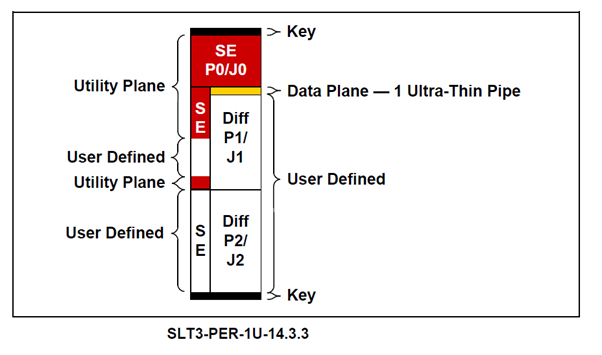
Where the x1 PCIe Host Interface signals are routed to data plane. All of the User IO signals have been routed to the differential connector P2. The differential P1 connector has no User IO signals routed to it in order to enable the EXC-8000ccVPX to be compatible with the following additional VITA 65 profiles:-
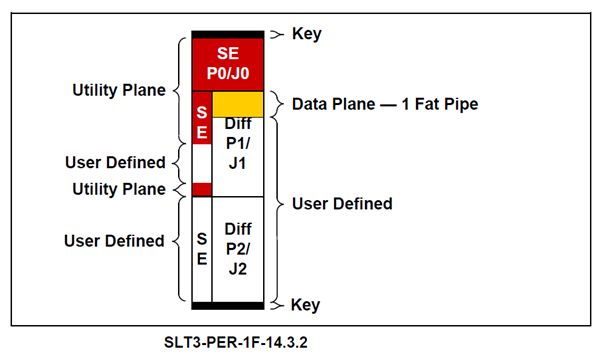
SLT3-PER-1F-14.3.2 (x4 PCIe) – (4 Tx & 4 Rx)
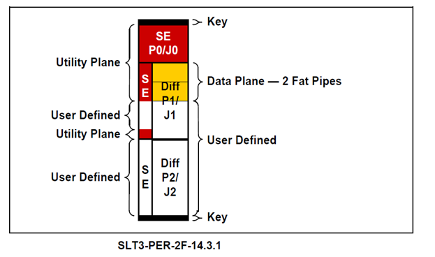
SLT3-PER-2F-14.3.1 (x8 PCIe) – (8 Tx & 4 Rx)
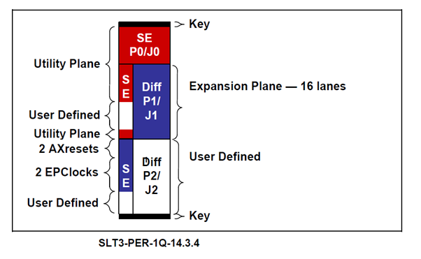
SLT3-PER-1Q-14.3.4 (x16 PCIe) – (16 Tx & 16 Rx)
These profiles have their PCIe Host Interface signals routed to the P1 differential connector as shown below. Thus, the EXC-8000ccVPX can be inserted into the VPX Backplane that supports any of the above slot profiles and will communicate seamlessly via it’s 1x PCIe pipe interface.
In the VITA 65 Specification recommends that eco-systems gradually migrate to using only the following power inputs from the backplane: 12 VDC, 3.3V_AUX, and VBAT. It is for this reason the EXC-8000ccVPX was designed by default to run solely the 12VDC supply from the back plane. However to provide backward compatibility the option for the following legacy power supplies was implemented as an optional feature : +5V, +3.3V.
Please see multi protocol 8000 modules for additional information on protocols that can be added to this card.
Ordering Information:
| Part Number |
Description |
| EXC-8000ccVPX/xx |
Multi-protocol interface for VPX compatible systems |
Note:
"xx” specifies the modules ordered with the carrier board (up to 4 modules) multi protocol 8000 modules.
"-001" added to the end of the part number specifies conformal coating option.
Mating Connectors & Cable Assemblies are NOT INCLUDED
| A0 - ARINC-429 |
Five ARINC-429 channels Software selectable for Receive or Transmit
|
| C0 - ARINC-708 |
Two ARINC 708/453 channels Software selectable for Receive or Transmit
|
| D0 - H009 |
One H009 channel
|
| F0 - MIL-STD-1553 |
One MIL-1553 multi-function Channel, Selectable for Transformer or Direct coupled mode
|
| H* - MIL-STD-1760 |
One single function channel
H1 = transformer coupled H2 = direct coupled
|
| I0 - Discrete I/O |
Ten Discrete Channels Software selectable for In/Out and TTL/Avionics 0-32 Volt thresholds
|
| J* - RS232/422/485 |
Two fixed RS-232/422/485 channels; RS-232 up to 1 Mbps and RS-422 or RS-485 up to 10Mbps
J1 = 2 channel RS-232 J2 = RS-232 / RS-485 J3 = RS-232 / RS-422
J4 = 2 channel RS-485 J5 = RS-485 / RS-422 J6 = 2 channel RS-422
|
| L0 - MIL-STD-1760 |
One MIL-1760 multi-function Channel, Selectable for Transformer or Direct coupled mode
|
| M0 - MIL-STD-1760 |
Monitor only (transmit disabled)
|
| N* - ARINC-717 |
Two channels Rx/Tx, HBP or BPRZ signals
N1 = HBP N2 = BPRZ
|
| P* - ADDA |
up to 10 single ended, or 5 differential, digital-to-analog (DAC) output channels, as well as 5 single ended or 5 differential analog-to-digital (ADC) input channels.
P1 = DAC outputs only (10 Single Ended or 5 Differential)
P2 = ADC inputs only (5 Single Ended or 5 Differential)
P3 = Combined DAC and ADC
(4 Single Ended or 2 Differential DAC outputs and 3 Single Ended or 3 Differential ADC inputs)
|
| R5 - MMSI |
Five channels meets requirements of AS5643, 10Mbps 1553 Protocol/RS-485 Transceivers
R5 = 5 EBR-1553 hub ports and 1 cBM port
|
|
S5 - ARINC-825
(canbus)
|
Five channels
S5 = 5 ARINC-825 channels
|
| T* - MIL-STD-1553 |
One single function channel
T1 = transformer coupled T2 = direct coupled
|
| V* - MIL-STD-1553 |
Monitor only (transmit disabled)
V1 = transformer coupled V2 = direct coupled
|